Choosing a Staic Frequency Converter is a practical engineering decision, not a simple catalog purchase. The correct unit must match the equipment, site conditions, and operating schedule. A converter feeding an aircraft test bench faces different demands than one supporting a factory motor. The details matter.
Power-electronics authority Dr. Paresh C. Sen offers a useful design principle: “Start with the application, then choose the converter.” This advice keeps attention on input voltage, output frequency, phase configuration, kVA capacity, waveform quality, and allowable distortion. A 50 Hz supply may need conversion to 60 Hz. A sensitive laboratory load may also require stable voltage regulation and low harmonic content. Motor loads can demand short-term starting current well above their running rating.
This guide explains how to compare these requirements before selecting a Staic Frequency Converter. It considers continuous load, peak demand, efficiency, cooling, noise, bypass arrangements, protection functions, and service support. Installation space deserves attention too. A compact cabinet can still produce substantial heat. Poor ventilation may shorten component life.
No selection is perfect. That is worth admitting. Buyers sometimes focus on purchase price and overlook maintenance access, spare parts, or future capacity. That assumption can fail when the load expands. Reliable decisions come from measured data, manufacturer documentation, and realistic site testing. The following sections provide a clear framework for evaluating converter performance, safety, compatibility, and long-term operating value.
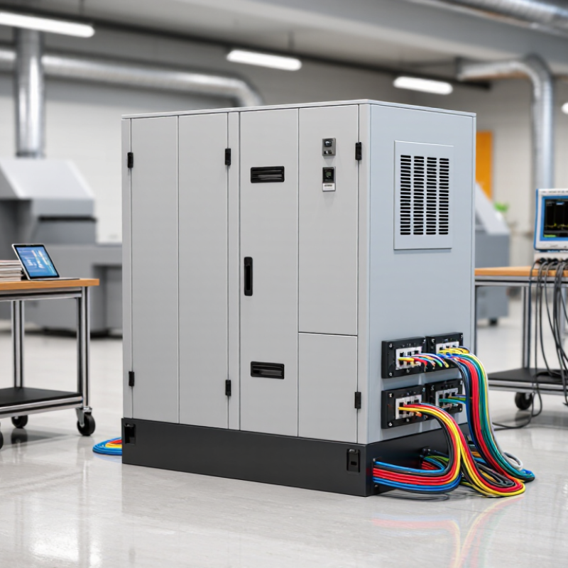
How to Choose a Static Frequency Converter?
Define the Power Conversion Requirements
Choosing a static frequency converter starts with accurate load information. Record the input voltage, output voltage, phase configuration, and required frequency. A converter for 400 V three-phase power differs greatly from one serving a 115 V single-phase load. Confirm the required output frequency, such as 50 Hz or 60 Hz, before comparing equipment.
Measure the load in kVA, not only kilowatts. Motors, transformers, and compressors can draw several times their rated current during startup. A converter that matches the running load may trip immediately. Check the starting current, duty cycle, power factor, and whether the load changes rapidly. Sensitive equipment may also require low distortion, tight voltage regulation, and electrical isolation. In practical assessments, missing one small motor can change the sizing decision. That oversight is easy to make.
Tips: Create a simple load schedule with voltage, frequency, kW, kVA, startup current, and operating hours. Include future equipment, but avoid excessive oversizing because light loading may reduce efficiency. Check ambient temperature, altitude, ventilation, and available installation space. These conditions affect continuous output. Review the specification with a qualified electrical professional, especially when several loads share one converter. A test under real operating conditions is valuable. Paper calculations can still miss unexpected startup behavior.
Start by identifying the nominal input voltage and frequency at the installation site. The chart compares common electrical profiles that may need to be converted before specifying the converter’s output voltage, output frequency, phase configuration, and power capacity.
North American systems commonly use 120 V at 60 Hz, while many European and Australian systems use 230 V at 50 Hz. Japan uses 100 V, with 50 Hz in eastern regions and 60 Hz in western regions. Final selection should also account for connected load kW or kVA, starting current, duty cycle, phase type, allowable voltage tolerance, and the required output frequency.
A static frequency converter should be selected by comparing input, output, and frequency specifications together. Start with the input source: voltage, phase, allowable fluctuation, short-circuit capacity, and harmonic content. A 400 V, three-phase, 50 Hz supply may not deliver stable power during motor starts. Check the converter’s input range under real operating conditions, not only its nominal rating. IEC 61000-2-2 identifies 8% total harmonic distortion as a compatibility level for public low-voltage systems. Excessive distortion can increase heating and trigger protection trips.
The output specification must match the load’s behavior. Confirm continuous kVA, overload duration, voltage regulation, waveform quality, and transient response. Sensitive laboratory equipment may need tighter regulation than a simple resistive heater. Frequency accuracy also matters. A 50-to-60 Hz conversion can affect motor speed, cooling, and pump flow. IEEE 519-2022 commonly applies a 5% voltage THD planning level at the point of common coupling for systems up to 1 kV. However, a clean output does not guarantee correct equipment performance. Cable length, inrush current, and load imbalance still matter. Specification sheets can look precise, yet field conditions remain imperfect.
Tips: Measure the existing supply for at least one operating cycle. Record voltage dips, frequency drift, and startup current. Ask for efficiency at your actual load, not at full capacity. Leave practical headroom, but avoid excessive oversizing, which may reduce efficiency and regulation. Recheck the frequency requirement when motors or transformers are involved. Small assumptions become expensive faults.
A static frequency converter should match the real load, not just its nameplate rating. Check the equipment’s voltage, phase, frequency, power factor, and kVA demand. Motors may draw five to seven times their running current during startup. That surge can trip an undersized converter.
Review the load type carefully. Resistive heaters are usually predictable. Motors, pumps, compressors, and transformers create stronger inrush demands. Variable-speed drives and switching power supplies can also introduce harmonics.
Confirm that the converter tolerates the load’s crest factor and nonlinear current. A clean output waveform matters. Sensitive instruments may react badly to distortion or brief voltage changes.
In field commissioning, I compare measured startup current with the manufacturer’s published overload curve. A neat spreadsheet is not enough. Record the load while it starts, runs, and stops. Check output frequency stability, voltage regulation, response time, cooling airflow, and efficiency at both light and peak loads.
Leave practical headroom, often 20 to 30 percent, rather than operating continuously at the limit. It may seem excessive. It can prevent nuisance shutdowns and overheating.
Also verify compatibility with protective devices and the installation environment. Dust, heat, and restricted ventilation quietly reduce performance. If the application includes several loads, test their combined behavior instead of adding ratings mechanically. That shortcut is easy, but not always reliable.
How to Choose a Static Frequency Converter?
A static frequency converter should fit the installation, not merely match the nameplate. Check the incoming voltage, phase arrangement, frequency, and available fault current before selecting capacity. Confirm the connected load’s starting current, especially for motors, pumps, and laboratory equipment. A converter running near its maximum rating may work today but overheat during summer operation. Leave practical headroom.
Installation details often decide long-term reliability. Provide clean, dry space with enough clearance for airflow and service access. Dust can block filters, while excessive heat can shorten component life. Verify grounding, cable sizing, ventilation, and enclosure protection against the site environment. In a coastal or washdown area, a suitable IP rating matters. Do not assume the existing electrical cabinet is adequate. That assumption is risky.
Protection functions should include overload, short-circuit, overtemperature, phase loss, and abnormal input detection. Select adjustable limits carefully, because overly sensitive settings can cause nuisance shutdowns. Maintenance should include visual inspections, terminal checks, filter cleaning, and recorded temperature readings. Use the manufacturer’s service intervals, but adapt them to actual dust, humidity, and operating hours. A maintenance log reveals gradual changes that memory misses. Perfect planning is unrealistic. Even a well-designed system may need adjustment after real operating conditions appear.
| Selection Dimension | What to Check | Typical Requirement or Data | Why It Matters | Recommended Action |
|---|---|---|---|---|
| Input Voltage | Confirm the available utility or generator voltage and phase configuration. | Common industrial inputs include 208 V, 220 V, 380 V, 400 V, 415 V, or 480 V; systems may be single-phase or three-phase. | An incorrect input rating can cause undervoltage, overvoltage, overheating, or converter failure. | Match the converter input range to the measured site voltage, not only the nominal value. |
| Output Voltage and Frequency | Identify the voltage and frequency required by the connected equipment. | Typical output frequencies are 50 Hz or 60 Hz. Output voltage must match the equipment nameplate and insulation rating. | Motors, pumps, compressors, test equipment, and aircraft-support loads may require different frequency standards. | Specify both output voltage and frequency, including acceptable voltage and frequency tolerance. |
| Rated Power | Calculate the connected load in kW or kVA, including starting and transient demand. | For mixed loads, size by apparent power in kVA. A practical design margin is often 20%–30% above the expected continuous demand. | Insufficient capacity can produce nuisance trips, voltage sag, excess heat, and reduced service life. | Use the highest continuous demand plus motor-starting, inrush, and future expansion requirements. |
| Load Type | Classify the load as resistive, inductive, capacitive, nonlinear, or mixed. | Motors and transformers create inrush current; rectifiers and switching power supplies may introduce harmonic currents. | Static converters do not respond identically to every load profile, especially during starting or rapid load changes. | Check overload, crest-factor, inrush-current, and short-circuit performance before approval. |
| Efficiency and Heat | Review efficiency at the expected operating load and determine heat dissipation. | Power-electronic converters commonly operate at approximately 90%–98% efficiency, depending on topology, rating, and load. | Even a small percentage of power loss becomes heat that must be removed from the enclosure or room. | Provide ventilation or air conditioning based on calculated losses, ambient temperature, and altitude. |
| Installation Location | Assess indoor or outdoor placement, available floor or wall space, dust, moisture, vibration, and access clearance. | Keep air inlets and outlets unobstructed. Many power-conversion enclosures are intended for controlled environments unless a higher enclosure rating is specified. | Poor installation conditions can restrict cooling and accelerate corrosion or insulation deterioration. | Confirm enclosure rating, mounting method, cable entry, service clearance, and environmental limits. |
| Ambient Conditions | Check operating temperature, humidity, altitude, and contamination level. | Performance may be derated above the equipment’s specified ambient temperature or installation altitude. Condensation should be prevented. | High temperature and altitude reduce cooling capability and may require output derating. | Apply the manufacturer’s derating curve and consider heaters, filters, or pressurization where appropriate. |
| Protection Functions | Verify protection against input faults, output faults, overload, overheating, and abnormal voltage or frequency. | Useful functions include overcurrent, short-circuit, overtemperature, phase loss, under/overvoltage, and emergency shutdown. | Protection limits equipment damage and helps isolate faults before they affect the wider electrical system. | Select a unit with protection thresholds suitable for the load and coordinate it with upstream and downstream breakers. |
| Power Quality | Review output waveform, voltage regulation, frequency accuracy, total harmonic distortion, and electromagnetic compatibility. | Requirements depend on the sensitivity of the load. Precision equipment generally needs tighter regulation and cleaner output than heating loads. | Poor power quality may cause motor heating, control errors, nuisance alarms, or interference with instrumentation. | Request verified performance data at the intended load range, including nonlinear-load conditions where applicable. |
| Grounding and Cabling | Confirm protective earth, neutral requirements, conductor sizing, cable length, and separation from signal wiring. | Grounding and bonding must comply with local electrical codes. Cable ratings should account for current, temperature, grouping, and installation method. | Correct grounding reduces shock risk, electromagnetic interference, and damage during fault conditions. | Have the wiring design reviewed by a qualified electrical professional before energization. |
| Controls and Monitoring | Determine whether local controls, remote start/stop, alarms, data logging, or communication interfaces are required. | Common signals include dry contacts, analog measurements, and industrial communication connections. | Clear status information speeds troubleshooting and supports integration with facility-control systems. | Define required alarm contacts, permissives, interlocks, and communication points in the specification. |
| Maintenance Access | Check accessibility of fans, filters, capacitors, cooling paths, terminals, and diagnostic indicators. | Maintenance intervals vary with duty cycle and environment. Dusty or hot locations generally require more frequent inspection. | Restricted access increases downtime and makes routine inspection less likely to be completed correctly. | Allow safe working clearance and choose a design with accessible service points and clear fault codes. |
| Inspection and Cleaning | Plan periodic checks for dust accumulation, loose connections, corrosion, abnormal noise, and signs of overheating. | Inspection frequency should be risk-based; high-load, dusty, humid, or critical installations need closer monitoring. | Early detection can prevent cooling failure, insulation damage, and unplanned shutdowns. | Record inspection results, torque checks, temperature observations, and corrective actions in a maintenance log. |
| Cooling Components | Review fan type, expected service life, filter arrangement, and availability of replacement parts. | Fans and filters are wear or maintenance items. Blocked filters increase pressure drop and reduce airflow. | Cooling-system failure is a common cause of thermal alarms and converter derating. | Keep critical spare fans and filters available when downtime has a high operational cost. |
| Safety and Isolation | Verify disconnecting means, lockout/tagout provisions, discharge time, warning labels, and internal barriers. | DC-link capacitors can retain hazardous energy after input power is removed; the required waiting and verification procedure must be followed. | Safe isolation protects personnel during inspection, testing, and repair. | Use documented isolation procedures and verify absence of voltage with properly rated test equipment. |
| Compliance and Documentation | Check applicable electrical, EMC, safety, and installation requirements for the project location. | Required documentation may include wiring diagrams, installation instructions, test reports, protection settings, and maintenance schedules. | Complete documentation supports safe commissioning, inspection, troubleshooting, and future replacement. | Do not release the purchase specification until ratings, interfaces, environmental limits, and service requirements are documented. |
How to Choose a Static Frequency Converter?
Select a Converter Based on Cost and Long-Term Value
The lowest purchase price rarely represents the lowest total cost. A static frequency converter may run continuously for years, making efficiency, cooling, and service access financially important. Compare the converter’s rated output with your real load, not only the equipment nameplate. Motors, testing systems, and sensitive electronics can draw higher current during startup. That detail matters.
Check input and output frequency ranges, voltage tolerance, waveform quality, and overload capacity. A stable output can protect connected equipment and reduce unexpected shutdowns. Ask for measured efficiency at 25%, 50%, and 100% load. One figure is not enough. Also inspect harmonic distortion data and thermal derating information. A unit that performs well in a cool workshop may struggle inside a hot electrical room.
Maintenance costs deserve equal attention. Review filter replacement intervals, fan life, fault records, spare-part availability, and technician training requirements. A clear manual and accessible service panels can reduce downtime. Calculate energy costs over five or ten years, then include installation, testing, repairs, and disposal. The result may challenge your first choice. Still, calculations can be imperfect when operating hours change. Use realistic site data, and leave a reasonable margin. Long-term value is not simply a larger warranty. It is dependable performance, measurable efficiency, and support that remains practical after installation.
Record input voltage, output voltage, phase configuration, and required frequency.
Use kVA as well as kilowatts.
Leave practical capacity for startup and changing loads.
Check ambient temperature, altitude, dust, humidity, ventilation, and installation space.
Confirm grounding, cable sizing, airflow, service clearance, and enclosure protection.
Look for overload, short-circuit, overtemperature, phase-loss, and abnormal-input protection.
Perform visual inspections, terminal checks, filter cleaning, and temperature recording.
A real-load test is valuable, especially when several loads share one converter.
Choosing a Staic Frequency Converter begins with clearly defining your power conversion requirements, including the equipment type, rated power, operating environment, and expected duty cycle. Next, compare the converter’s input voltage, output voltage, phase configuration, and frequency range with the requirements of your application. These specifications should provide stable and accurate power for the connected equipment.
It is also important to evaluate load compatibility, overload capacity, waveform quality, efficiency, and response performance. Before installation, check the converter’s protection functions, cooling method, space requirements, wiring conditions, and maintenance needs. Finally, consider the total cost of ownership rather than focusing only on the purchase price. A reliable converter with suitable protection, efficient operation, simple maintenance, and a long service life can provide better long-term value and reduce unexpected downtime.

Bangzhao Electric